There are two sets of vector arrays. How to create the following custom graphic.
contoursDown is the lower contour vertex.
contoursUp is the lower contour vertex.
The pictures are models generated by other software
The x and y values are almost the same, apparently these are the surfaces that lie at a constant distance of 1.5 (z values).
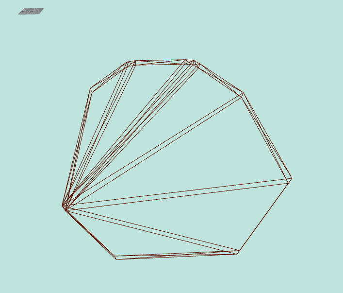
However, I only count 8 corners. What does it look like if you draw the 11 points in a coordinate system? As a rough sketch.
The pictures are better, but do not show the discrepancy 8 to 11. Draw only the x, y coordinates (lower) approximately in a 2D coordinate system.
11 is the number of vertices of each contour, not the number of edges when looking at the picture
The corners and edges visible without wireframe are identical 8.
To form triangles, your other software may use additional vertices that cannot be seen in your images. That’s why you need the sketch to recognize the principle.
There are also additional vertices in these examples.
Now you can see what you can also see in the first pictures if you look very closely. There are closely spaced vertices which, roughly speaking, look like a corner.
It is a very special triangulation that your software provides. I can see the division into 4 instead of the usual 2 triangles in the frame. You can do something like this, see Rounded corners on BoxGeometry where faces not touching - #4 by hofk
Do you have to process exactly this existing data and get the identical wireframe?
Yes, must use the array data exactly
I’m sorry to interfere in your discussion. Creating custom geometry would require:
My suggestion for this specific case is to use a CylinderGeometry with 11 radial segments. This will create the structure of the object. Then just populate the coordinates in the created buffers.
My exact question was whether the exact wireframe has to be created for some reason. The cylinder has a center vertex at the top and bottom but no other center vertex. That is the difference and if that is irrelevant, you can use the cylinder.
I tried using cylinder, but I couldn’t correspond to its vertex data
It is difficult to help you because your questions and answers are too brief and imprecise.
Please post the code you have tried. It is best to use a live example (e.g. Codepen, JSFiddle).
In these examples from the collection you can see how to access the vertices and change the shape.
CurvedArrowHelper
SineWaveGrooveRing
You can see the arrangement here: NumberingHelperExamples
In some places, vertices are in the same place!
I tried using a cylinder to modify the vertices, but it couldn’t correspond to my vertex data.
@a627247084
What you provided is screenshots/gifs of console with array data and wireframe object.
Any chance to provide a working live code example? jsfiddle, codepen, codesandbox etc.
After the Boolean operation, those holes have no faces
I tried using planGeometry to perform Boolean operations. The holes have faces, so Boolean operations are no problem.
@prisoner849 @hofk
Is the model in the above example not closed?