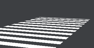
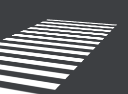
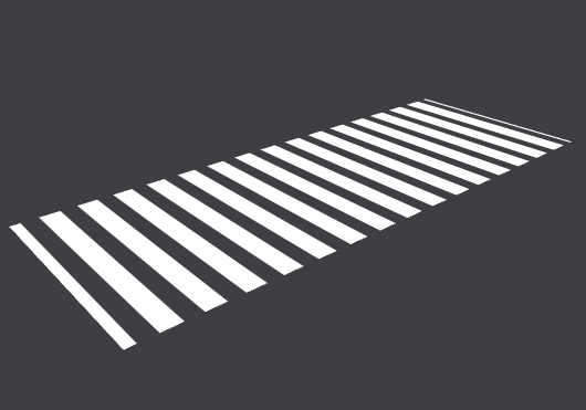
Like this demo, how to adjust the shader code to keep zebra stripes always vertical
Vertical as in parallel to the rectangle’s edges or as in parallel to the browser window edges?
I hope it is parallel or perpendicular to the edge of the rectangle
The shader code creates stripes following uv coordinates attached to the shape’s vertices, so one way is to overwrite them to a standard [0,0] - [0,1] quad values:
  const shapeGeo = new THREE.ShapeGeometry(new THREE.Shape(points));
  // ADD THE CODE BELOW
  // ------------
  const stripes = 5;
  shapeGeo.setAttribute('uv', new THREE.BufferAttribute(
    new Float32Array(
      [0,0, 0,stripes, 1,stripes, 1,0]
    ),
    2));
// --------------
also, there is a small glitch that produces a thin outline on one edge of the shape, not sure why, didn’t have much time to think about, something overflows into negative, to fix it change this line in the shader code:
float strength = mod(vUv.y, 1.0);
to:
float strength = mod(abs(vUv.y), 1.0);
link:
https://stackblitz.com/edit/stackblitz-starters-wtoejq?file=index.js
I’m sorry, actually I want the stripes to be perpendicular to the longest side of the shape, so they look very similar to real zebra stripes. Do you have any other ideas?
The problem is that your shapes are defined with different aspect ratios, some of them are horizontal and some vertical. To fix that you could swap shape points:
  const points = shape.map((point) => new THREE.Vector2(point.x, point.y));

// NEW CODE HERE
  const side1 = new THREE.Vector2().subVectors(points[0], points[1]);
  const side2 = new THREE.Vector2().subVectors(points[1], points[2]);
  const aspect = side1.length() / side2.length();
  let pnts = points;
  if (aspect > 1) pnts = [points[1], points[2], points[3], points[0]];
// --------
  const shapeGeo = new THREE.ShapeGeometry(new THREE.Shape(pnts));
  const stripes = 5;
I have made adjustments according to the idea you provided, and now I can correctly display zebra crossings in all directions based on the aspect ratio. However, I have found that there are jagged edges, and the degree of jagged edges is different. May I ask why
https://stackblitz.com/edit/stackblitz-starters-fy9ugu?file=index.js
You mean jagged edges like this?

This happens due to
- the fact that the shader code doesn’t have any texture, it uses math to paint stripes, so you don’t have any anti-aliasing that can be achieves with textures
- how
stepfunction works in the shader code, it abruptly changes value from 0 to 1, so when projected on the pixel grid at some angles, it looks jagged
This can be fixed by using smoothstep instead, like so:
 float strength = mod(abs(vUv.y), 1.0);
      //strength = step(0.5, strength);
      float blur = 0.1;
      strength = smoothstep(0.5 - blur, 0.5, strength);
here I smoothed one edge, so you can see the difference:

with both sides smoothed:
strength = smoothstep(0.5 - blur, 0.5, strength) * smoothstep(1.0, 1.0 - blur, strength);

this is equal to fract(vUv.y) ![]()
Not sure how correct this approach is, but I tried:
    void main() {
      vec2 fUv = fract(vUv);
      float strength = abs(fUv.y - 0.5);
      float blur = length(fwidth(vUv));
      strength = smoothstep(0.25 - blur, 0.25, strength);
      gl_FragColor = vec4(customColor, strength); // 使用自定义颜色和透明度
    }
having this

shame on me ![]()
but realistically, it needs to be:
float strength = fract(abs(vUv.y));
otherwise there is a thin line at the beginning, as I mentioned earlier, not sure why

Ah, slight correction:
    void main() {
      vec2 fUv = fract(vUv + vec2(0., 0.5)); // added vec2(0., 0.5)
      float strength = abs(fUv.y - 0.5);
      float blur = length(fwidth(vUv));
      strength = smoothstep(0.25 - blur, 0.25, strength);
      gl_FragColor = vec4(customColor, strength); // 使用自定义颜色和透明度
    }
gives this:

Thank you very much for your reply. This will deepen my understanding of the colorizer code. Thank you again