I am attempting to create an extended material which will allow me to change the height of vertices in a plane. That part works, but thee is an unexpected side effect. It appears that the object center is somehow displaced.
Here is a pen which illustrates this problem.
On the bottom are 4 adjacent planes that use a normal map. I have create a small gap so you can see the placement of the individual planes.
On top are 4 outer planes created with an extended material designed to allow me to change the height of the plane vertices and colors. As you can see, these planes are displaced outwards by 2X the distance they should be. I inserted a 5th plane in the center to show that the center of the texture is still in the right place.
Questions:
- What is causing the top planes to be offset by double the expected value?
- Why isn’t the appearance of the extended texture on the top planes about the same as the texture on the bottom planes?
Try to change this line:
transformed = pos;
to this
transformed.y = pos.y;
Thanks! That solved the position issue.
I figured out the appearance issue. A few lines above, I just needed to change objectNormal to vNormal. Now they are identical in appearance.
The last part of this effort was to enable the changes to the fragment shader which should result in changes to the water color based on height. But enabling those changes had no effect.
However they did work if I changed the normalMap to a bumpMap. (And it actually looks better!)
So I suspect that to make the normalMap work, some additional changes to the fragment shader are required.
One last question that was difficult to spot and did not appear until I started moving the planes.
It turns out that, even though the planes are moving, the waves are not moving along with them. I think it has to do with the use of modelMatrix, which appears as part of the computation of normals:
vec3 p = vec3(modelMatrix * vec4(position, 1.));
vec2 move = vec2(1, 0);
vec3 pos = moveWave(p);
I find that I am able to fix the problem if I change the first line to:
vec3 p = vec3(vec4(position, 1.));
But I am concerned that I might be losing something by removing modelMatrix. Or is that unnecessary where you are using moving planes?
I’m still curious, why do you want to move those planes at all, when you can simply simulate movement, moving just waves of ocean, using a single plane for that?
As a ref to what I mean: Endless way II (single plane)
Or don’t move the plane at all.
Here is a first effort to create random ocean waves using the sum of several sine waves plus a main Gerstner wave. This includes variations in color plus random whitecaps. I have resized this to my standard small grid size of 1/2 mile. The primary waves are about 4 meters tall (12 feet) and - based on standard wave data - there are about 10 rows of them in the grid. Not especially great looking, but this is just a first effort.
I have read that “Sea of Thieves” probably uses this kind of layering of waves to create their effects (called the FFT or Tessendorf method). But to match theirs, I probably need a much higher resolution mesh. But that would likely be overkill since I am not floating in the waves, but will be flying over them at much higher speed.
The reason I am using moving grids is because that is standard practice with flight simulations - which model both land and water. While waves are in motion, land is stationary - so once you set vertex positions on land, it seems that, instead of shifting all the vertices, it would be quicker to just move the entire square, I have read that the creation of waves using sums of sine/Gerstner waves is very grid friendly as long as you have a fixed number of waves in the grid.
From what I have read, there is currently a split in designs of ocean wave simulations - some use moving grids while others use fixed grids.
Regarding moving grids, I ran across a discussion of a tiling method of creating waves by precomputing FFT values and creating look-up tables (including Butterfly Maps) to compute vertex heights for nearby and distant grids. As far as I can tell, there is no discussion of this topic on this board and Google is not much help either. Here is a twitter post which explains this method.
EDIT: I forgot to add a reference to a Master’s Thesis by Thomas Bedrnik which discusses this topic in depth and - more importantly - contains shader code to implement this method…
But, as you say, there are advantages to using a fixed grid. Here is an article that discusses radial tessellation (instead of square grids) to determine level of detail.
I like the demo.
It helps that you are at ground level where your maximum visibility flat plane visibility is around 1 mile or so. You can test this by creating an object 6 feet tall and testing to find the distance where the top of the object merges into the ground. The curvature of the earth would make the object disappear at around 3 miles.
So, at ground level, the textured or animated flat plane only needs to extend out a mile or so. You could either add a vertical map or a big horizontal plane to make the ground reach up to level. (In your example, you have the path reaching out to the vanishing point.
However, in my projects, I am generally high above the ground and moving quickly. The former increases the required size of the visible plane. So I generally need to create planes that are visible out to 50 miles. The latter means that I cannot give the nearby terrain the same level of detail that I would if I were walking slowly. Flight simulators have traditionally handled these challenges by using scrolling grids with different levels of detail. In theory, you could do the same thing with a radial scale. But it is hard to imagine converting flat maps to a radial view. However, there are environments where a radial scale could work well - as in space combat where you are dealing more with discrete objects than a continuous plane.
One problem I noticed in your example is that the texture on your path turns fuzzy too soon. I ran into the exact same problem when creating procedural farmland when viewed from ground level. You can see the same effect on this example if you move the viewer down to ground level. The rows of crops quickly become fuzzy. This is a flat plane of 1/2 mile square (a quarter section). I am able to generate a high level of detail (a few inches per pixel) by repeating the 512x512 texture about 20 times. I suspect the mip-mapping - which avoids moiré distortions - is also causing this fuzziness. Let me know if you find a way to prevent flat textures from going fuzzy at short distances.
One last post on this topic.
I have been trying to create random waves by piling on waves from different directions and have had some success. However, the main problem is that all these changes are “smoothed out” and you don’t see a random texture. Instead you get more of a cartoon effect.
I have concluded that the best approach is “probably” to create integrated pre-computed scrolling maps for everything: vertex position, and normals along with diffuse and normal maps. These would be pre-computed for a specific sun position, etc. I could create a few variations to avoid a tiling effect.
As I try that out, I am sure I will have some questions that I will post to a new topic.
In the meantime, I had a “happy accident” (as Bob Ross would say) which has resulted in a version which - at least to me - appears to be showing sea foam (one of the hardest effects to model). The reason for this “foam” is that the sun is straight overhead and the standard three.js ocean normal map creates shiny patches that, when viewed from the side, look like sea foam. If you look straight down, you will see that this is all reflective. Let me know if you agree that this looks like sea foam - or if it is just me. If so, I will try to take advantage of this effect when creating my textures.
@phil_crowther
Your discussion with @seanwasere on Animated Ocean Waves, inspired me to make this small sketch about flight over waves  https://codepen.io/prisoner849/full/PoaZjWJ
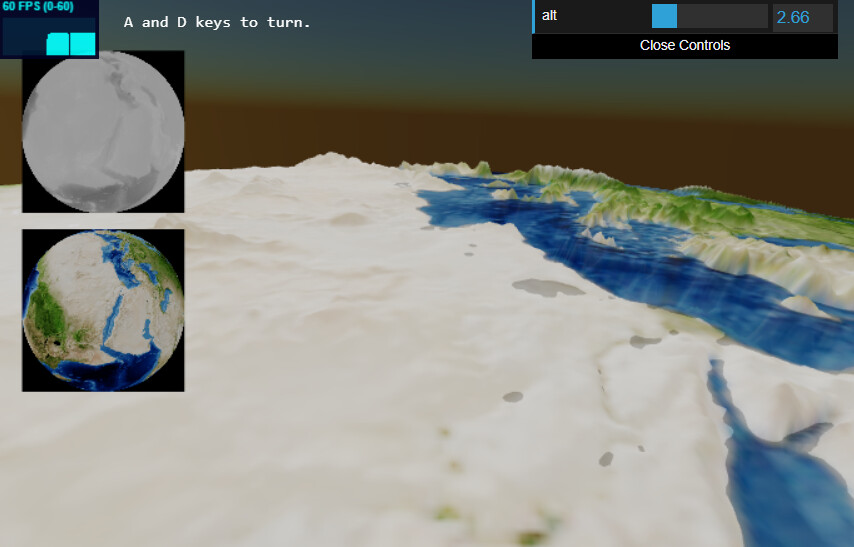
Cool, I made something quite similar.
Fly Earth (sbcode.net)
Great minds must think alike!
Just today, I started experimenting with MeshToonMaterial and I think it may actually help solve some of the problems I have been wrestling with. To compare:
Here is the original diorama.
Here is the revised diorama using MeshToonMaterial.
(The characters on the ship are for the amusement of the grandkids who are now playing “Sea of Thieves” and previously enjoyed playing “Castle Crashers”.)
The toon version is worse in that removes some of the “noise” from the original version and makes the wave repetition more apparent. On the other hand, this method may help generate some of the colors I have been looking for. My experience in ocean-watching was that there seemed to be very few colors - primarily, the natural color of the ocean and the color of the reflected sky as affected by sunposition. And, with a few more sine waves, I may be able to reduce the repetitiveness.
Also, I noticed that the toon version has a built-in ability to use a displacement map. It appears that the material uses that information to color individual pixels. If so, that may be helpful in doing things like displaying sea foam
That is amazing. I was not aware that you had already worked on something I was going to work on in the future - i.e. applying what I have learned about displacement of oceans to the displacement of land.
In the grid system I was using, the basic unit is 1/2 mile square. As it turns out, by dividing the square into 9x9 segments, I could use a 90 meter grayscale map (aka a 90m dem) to compute the vertex elevation.
I will have to explore the possibility of using WebGLRenderTarget for this purpose.
The boat looks good.
I researched but failed to find a workable solution to have flapping sails that could be extended to produced realistic lift, and drag.
Also, I’m not sure if using WebGLRenderTarget is the best solution for this. I was just experimenting. It does however mean I don’t need to have so many vertices in the scene, since the textures are being partially used. And it is also a quick solution to project my wgs84 textures spherically without using any complicated trigonometry.
But I have a simpler solution here.
Material Repeat and Center (use the bottom two X, Y sliders)
and another using shadows. DisplacementMap with Shadow
and another here Globe
I experimented with this here: LightNoise (selective bloom + noise)
Had to use this approach with WebGLRenderTarget as a displacement map for the sake of performance.
One heightmap shared to all the objects in the scene (exception is the glowing triangle) via a uniform.
In the past, I have created animated flags, etc. using linked parts and blender animations. For this model, I was considering doing the same using segmented planes and vertex displacement. Oddly, the concepts of lift and drag do apply to sails, especially modern boats with “wingsails”. I don’t plan to learn all that, but I might make it so that you can rotate ship and the sails to try to generate the most speed. When you are running with the wind, the sails would billow out.
Those resources will be very helpful when I stop fixating on waves and get back to terrain mapping.
That is really neat. Was it supposed to include sounds? I didn’t hear any, but I went to the YouTube video that provided you with the inspiration. So it is playing while I am watching the program. It reminds me of portions of the video game “Flower”.
This will also be helpful when I switch back to terrain mapping. Although I have argued that terrain shouldn’t be important with a flight simulation (especially an air combat simulation) since the goal is to avoid interacting with the terrain. However, I think most people would prefer to see something other than flat surfaces. And, my experience with re-creating islands indicates that you can create a fairly good looking island with a low poly grid if you can find a texture that is fairly detailed with the right shading.
And now that I am looking at your code, that may be more true than I originally thought.
After trying all kinds of combinations of sine waves (as many as 8) and even adding horizontal displacement (using the cosine function), I find that I cannot escape the dreaded tiling effect. So I am thinking that what I need to do is add some Perlin noise to the vertical displacement. It does not have to be truly random - but pseudo-random - so that the normal computations still work.
The best option appears to be to load in a Perlin grayscale texture and then look-up values from that texture. But I am not having any luck getting the vertex shader to read the values.
The address of the loaded texture is WtrMap. In the uniform (gu), I added this:
image: {value: WtrMap},
In the shader, I added:
shader.uniforms.image = gu.image;
and under shader.vertexShader =, I added:
uniform sampler2D image;
In the moveWave routine, I added the following instructions:
vec2 idx;
idx.x = p.x;
idx.y = p.z;
retVal.y = texture2D(image, idx).r;
It all assembles without errors, but it does not have any visible effect on the plane. (I removed the normal map and other displacement computations so it should show up clearly).
My assumption is that the look-up index for the texture (idx) is a combination of the xy values. I realize that the number of vertices is less than the number of pixels in the image, but referencing only part of the texture should not be a problem.
Thoughts?
What size of the surface you apply this texture to?
Each plane is 1000x1000 meters with 120x120 segments (or 121x121 vertices).
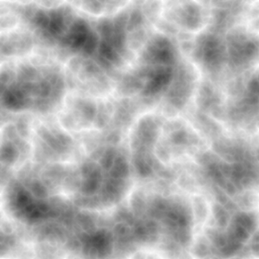
The random texture I am using is “https://threejs.org/examples/textures/water.jpg” which is a 512x512 grayscale texture.
Once I get this working, I can change the vertices to a multiple of 2, e.g. 64 or 128 and create a custom random terrain of the same dimensions where the border values are identical (to avoid creating a gap between adjoining grids).
EDIT
Or perhaps I can use a displacement map? It appears that you can scroll these like other textures.
I would want to use very small displacements (e.g. less than 5 meters). Or if the displaced Y-values are incorporated in the starting “position” used by the shader extension, perhaps I can modify those values so I am not limited to integer values…
This seems not correct for picking a color from a texture. You need to have a UV coord, which is in range 0..1 along both X and Y (U and V). For that I’d use
vec2 texUV = fract(pos.xz / 1000.);
retVal.y = texture(image, texUV).r;
