Mapping-fidelity in quadrilateral/triangle rendering

Friends of high-fidelity mappings :v:,

I left off with plain old texture mapping now working in a non-affine way, that is without any kinks in straight lines/features along the diagonals of trapezoidal quads. My last JSFiddle had temporarily stopped working because it referenced dat.gui.module.js which in the meantime has been replaced by the three.js project team with lil-gui.module.min.js . I updated the previous JSFiddle and it’s now working again. On that occasion I’m also hosting the texture maps I’m using in this JSFiddle on my own webspace, because I have better control over any CORS issues should they again arise.

Before I go on, I’d like to introduce my test 2k by 1k equirectangular map which I stitched together using PTGui Pro from single shots I took on a bike trip through the Swiss Alps (Klausenpass). For better reference, I added one-pixel wide vertical lines at the 0, 511, 1023 and 1535 pixel positions each:

View full size.

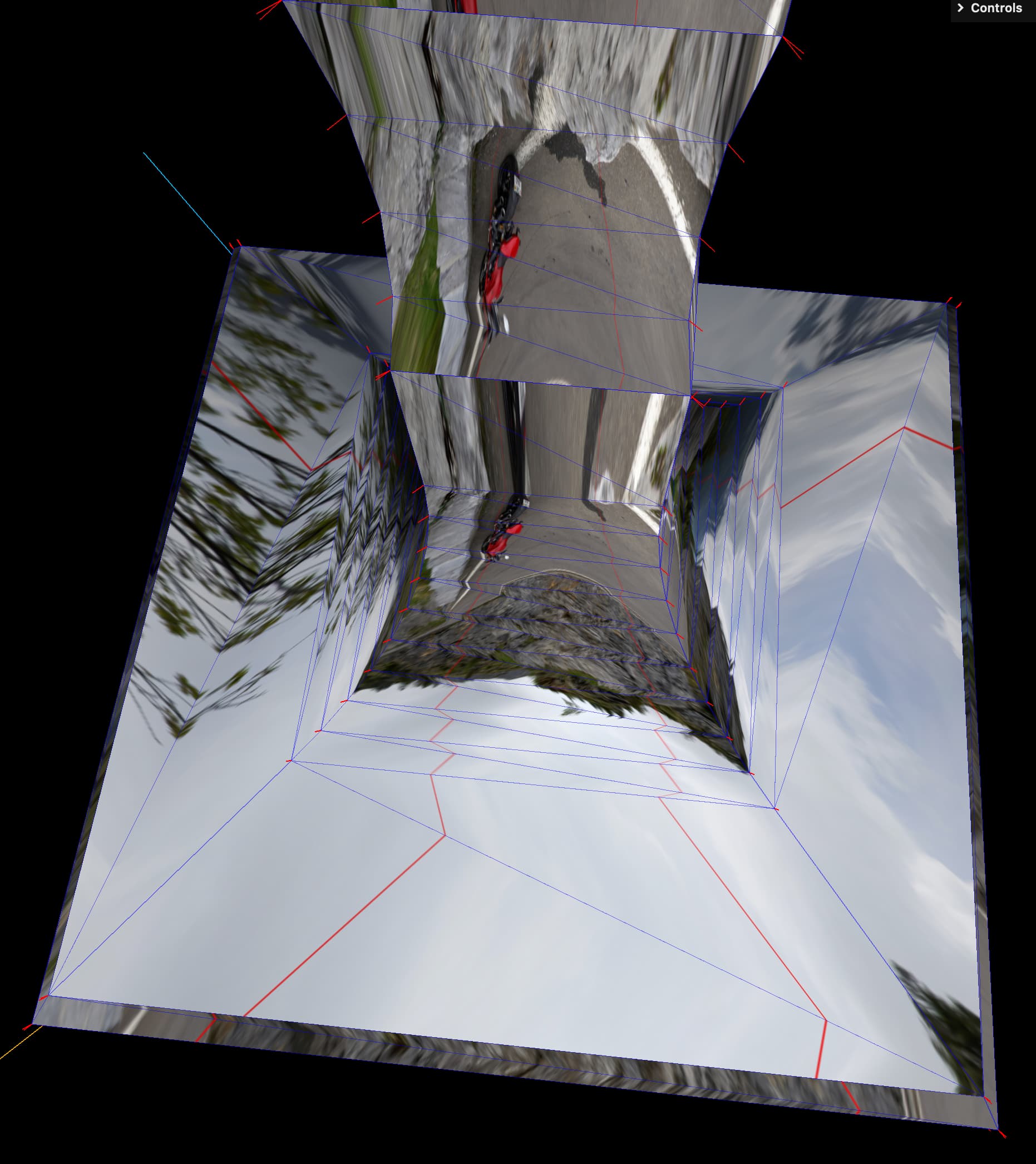
Those of you who have played (or are going to play) with the previos JSFiddle and select „reflective“ material and a lathe count of 4 segments will see (or have seen) something like this:

The above is the view straight down the lathing axis (y), overlayed (Gimp) with a wireframe rendering of the same scene.

I was expecting the general reflection to be „broken“ along the diagonals of the trapezoidal quads, but I was not expecting the straight red lines to display a behaviour as erratic as the above.

Which led me to look at the way vertex normals are computed in a LatheGeometry, because reflections are based on the evaluation of normals. I did find room for improvement, filed a PR which got accepted and which is going to be part of r136. For the „what“, „why“ and „how“ please refer to the description of that PR (#22927). The change introduced with that PR is a prerequisite for the following.

This is what the above rendering looks like with that PR applied:

Please note, that I’ve dedicated an evolved version of the previous JSFiddle for the following, as I didn’t want to loose the history by overwriting the previous one. Also please note, that this first fix only affects the “meridian” lines of the trapezoidal quads, not the content of the triangles yet. That said: Here we go!

And again overlayed with the corresponding wireframe rendering:

This is still not pretty, but the perfectly straight rendering of the vertical red lines of the equirect map indicates that now I have a sound basis for further work. Which I have already done and which I will introduce to you tomorrow.

Thanks for your attention.

P.S.: The bleeding red-ish triangles seem to be the result of some filtering applied during texturing.

prematurely released - sorry for the confusion. I’m still redacting this post.

Stay tuned …

Since I’m almost illiterate with respect to GLSL, I implemented a function to interpolate the vertex normals in JS, instead of the shaders. To find out early on if it’s worth the effort at all.
Spoiler alert: it definitely is!

This is my interpretation of the current (legacy) way of how the shaders interpolate triangle vertex normals, applied to the lower right wedge of the pentagon of my test geometry:

This is what the reflection, using the above interpolation of vertex coordinates and their respective normals, looks like:

The following is the proposed new way of bilinear interpolation of vertex normals for trapezoidal quads as generated by the LatheGeometry() function:

These are the resulting reflections:

Viewed straight-on:

Let the continuous flow of reflections between adjacent faces of the same wedge of the test geometry mesmerize you:

https://jsfiddle.net/Chrisssie/b6u17o9v/

I seem to have failed so far to demonstrate what the benefit of all this might be, in the context of reflection mapping. Using an obscure test geometry certainly has not helped either, I guess. So with the New Year comes a new trial! :slight_smile:

As a real-life example I’m now using an intake valve from the ICE of my Ducati motorcycle:


which I model as a Three.js LatheGeometry() using the following path:

Although I shortened the valve stem to bring the aspect ratio of this geometry for demo purposes closer to 1.0, this sample LatheGeometry features most of the situations which one can encounter in a real life lathed part:

  • cylindrical and flat circular/ring shaped sections (black)
  • concave rounded sections (green)
  • convex rounded sections (blue)
  • conical sections (red)
  • smooth transitions between different sections
  • sharp-edged transitions.

So it’s a pretty versatile test geometry after all.

When it comes to reflections, even tiny deviations from the (physically) true orientations of normals have a huge impact on reflection fidelity. This impact is most pronounced in very low segment-count LatheGeometries:


See the straight red lines of the equirectangular map being rendered as zig-zag, with the “zigs” following the diagonals of the quads that are the result of LatheGeometry().

I have put together a demonstrator which allows you to

  • see if there is a problem at all, and if so: how big it is.
  • crank up the lathe segment count, until you reach a satisfactory reflection quality
  • choose from two different maps, one photographic, one geometric
  • overlay/hide a wireframe display of the geometry, to correlate display faults with quad diagonals
  • show/hide a normals helper as an indicator of vertex locations
  • show/hide the background map.

The most interesting part (from my point of view) is the Tessellation slider, which allows you to tessellate each quad from the “base geometry” into Level * Level sub-quads, thus simulating (preempting) the effect which a suitable shader hopefully would be able to provide. This shader would have to do a more proper interpolation of vertex normals than the currently implemented solution. See for yourself of the remarkable quality of reflections which could(!) be achieved even with very low face / vertex count LatheGeometries.

Presented as a JSFiddle:

https://jsfiddle.net/Chrisssie/6qymkftg/

1 Like

Hello, I had trouble implementing this, in particular for irregular quadrilateral, because the solution given had hard-coded values (specific case of 3.0 factor), then I’ve found a general formula that works perfectly for me in Three JS, thanks to Nathan Reed’s blog :

Quadrilateral Interpolation, Part 1 – Nathan Reed’s coding blog (reedbeta.com)

1 Like

@EV_Robert Robert, thanks for posting this. The link you provided points to a well-written article which (for the most part) even non-mathematicians can follow through. Its continuation article with the bilinear interpolation sample was too “heavy” for me, and although the author provides in the implementation section some shader pseudo-code, I’m not familiar enough to even try to implement this myself. Although I do agree, that judging by the authors illustrations this seems (in principle) to hold the solution to my initial problem. Except, that it’s not mapping coordinates which need to be bilinearly interpolated, but normals.

Maybe someone else wants to take over from here, thinking of @prisoner849