This is driving me nuts. I managed to reproduce a simple case (my scenario is more complex, and the effect is worse) in this fiddle: three.js dev template - module - JSFiddle - Code Playground
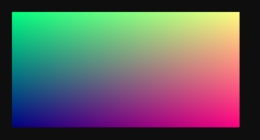
I’m doing some postprocessing over a pure gradient texture

( R component grows along the rows, G grows along the columns, B is fixed)
I’m using a basic shader which maps the texture along each row: for each target position (x,y), it copies the color from the texture at position (x + k t, y) where t is fixed and k is an integer chosen such that x + k t is near 0.5 (near the center vertical line).
It works as expected if I set mytexture.minFilter = THREE.LinearFilter; (uncomment line 73)

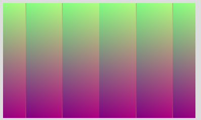
but with the default LinearMipmapLinearFilter, there are some issues, especially near the top

Recall the original texture has constant G channel along the rows, and the mapping is purely along the lines, hence the G channel should stay constant. Well, it doesn’t. Zoomed (showing the Red/Green components near the top). All is perfect, except for that vertical line of two pixels, for which the G component is totally wrong.

The problem is worsened if I use NearestMipmapNearestFilter (uncomment line 74):

Any idea what is happening here ?
Update
I’ve added a version with a base texture that is strictly constant along the rows, from (255,0,128) at top to (0,255,128) at bottom. So that the expected result is, also, constant along the rows.
And both the texture and the canvas are square now, with power-of-two dimensions.
The problem persists. It’s like near the top (and botton) it’s picking a bad y coordinate

With NearestMipmapNearestFilter :

I’m using Chrome with Windows 11. Some WebGL info:
{
  "card": "Intel, Intel(R) UHD Graphics 630",
  "manufacturer": "Intel",
  "cardVersion": "630",
  "brand": "Intel(R) UHD Graphics",
  "integrated": true,
  "vendor": "Google Inc. (Intel)",
  "renderer": "ANGLE (Intel, Intel(R) UHD Graphics 630 (0x00003E98) Direct3D11 vs_5_0 ps_5_0, D3D11)",
  "webGLShaderPrecisionFormat": {
    "precision": 23,
    "rangeMax": 127,
    "rangeMin": 127
  }
}
Another update:
With a simpler frag shader:
      vec2 uv = vUv;
	  float x = fract(vUv.x + vUv.y);
  	  vec2 uv2 =  vec2(x, uv.y);
(which, again, operates over each row, and hence should produce a constant image over each row) gives this:

Or, with
vec2 uv = vUv;
float x = clamp(fract(vUv.x * 3.137 ), 0.1, 0.9);
vec2 uv2 =  vec2(x, uv.y);
( added clamp just to check that the effect is not related to accesing the borders of the texture)

Again, the problem disappears with THREE.LinearFilter
Any help is appreciated.
Mipmaps hate discontinuities in texture coordinates. In this specific case, the discontinuity comes from using fract. I expect it should work fine if it is just float x = vUv.x + vUv.y;
1 Like
Yeah, it works ok without the fract. But in my scenario discontinuities are essential.
Is this a known problem, then? Any suggestion or pointer? Should I resign to use LinearFilter ?
Yes, it is a known problem. I have faced it too and I have not found any simple and universal solution.
See here the paragraph before the last one – I have also decided to turn off mipmaps:
https://boytchev.github.io/texture-generator/docs/about.html
If you find a good solution, please, let me know.
1 Like
Do you want to tile textures? Then you need repeat wrapping in the sampler settings of the texture. This ensures that exactly the continuity break that you get with fract does not occur when repeating.
Mipmaps are calculated by the system like this:
For a pixel with an even index, the difference to its right-hand neighbor pixel is formed in the fragment shader. For a pixel with an even index, the difference to its left neighbor pixel. That’s what dfdx does.
It works similarly with dfdy, pixels from odd columns form the difference to their pixels in the neighboring column below and vice versa.
These are differences in clip space, i.e. the screen coordinates.
This fragment difference is set in relation to the difference of the next texture pixels for these fragments. And the mipmap level follows from the log2 of this value. If you now have a continuity break between neighboring texture pixels because you repeat with fract, i.e. you create an edge without comparable neighboring pixels in the texture so that the difference cannot be formed with the neighboring texture pixels, then it looks like yours.
Repeat wrapping turns your texture to be tiled into a simulated larger texture in which your texture is contained multiple times and continues this process without interruption. The grid tiled with repeat wrapping is seen by the shader as one texture, so to speak, without consuming more memory. With tiles with fract, each fract interval is still a texture uv world in itself with edges.
Tiling textures with fract is unfortunately inherently associated with a break in continuity.
That was a lot of blah blah from me but I hope it helps you understand what the cause is.
2 Likes
Thank you very much for the explanation. I don’t exactly want to tile, not at least a regular one. I need to copy by hand parts of a texture (generating an autostereogram), doing sort of a horizontal varying (and highly discontinuous) tiling. I’m guessing, then, that I should give up using mipmaps…
1 Like
… but, thinking of it, what I know in advance is the approximate desired sampling resolution, hence perhaps I should try generating a few (2 or 3) mipmaps manually. I guess the strange colors I see come from a subsampled mipmaps, so perhaps it’s enough to avoid providing them to webgl.
Actually, it was not necessary to generate mipmaps in my scenario. It was enough to resize the texture on loading to the desired resolution and disable mipmaps.
Thanks for the help.


