I’ve been contemplating on how to make the wall functionality of a level-editor similar to the one in The Sims. I’ve found a few questions online regarding something similar, but I ran into some other issues than those discussed there, and I’m really curious on how the programmers actually solved this in the game. First off, drawing the walls without loading models could be done with shapes and extrusion or cubes. That gave a lot of issues. Here are some of my initial questions:
1: In the game (The Sims), walls seem to morph together when placed. How is this actually done? Are just more models created and placed next to those already there (overlapping vertices), or is there some advanced extrusion going on?
2. Corners of the walls can have all sorts of shapes. For instance, if I create a straight piece and then one at a 45 deg. opposite direction, the corner gets really pointy. How is this achieved? Is the model replaced?
3. Am I just over-complicating all of this, and is it much easier than I think? I must say that, when testing out The Sims, it seems more complex the more you analyze it. I can post some screenshots from The Sims for illustration later if necessary.
You are not overcomplicating things, unfortunately.
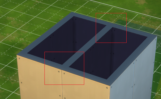
I have recently done a project with a furniture maker that included building rooms in the Sims-style. And boy, are the edge cases endless. I’d prepare to assume plenty of stuff and simplify on the way - Sims’ walls have 2 sides, they can angle, they can have cut-outs, windows / doors, “color entire wall strip” functionality etc.

(You can see at this point for example edge morphing wasn’t in place, nor were windows or doors.)
- What I’d suggest, unless you have to do otherwise, is do the wall calculations in 2D (basically a tile map with connections and types of walls) and then place models in 3D to fit the mapping. This results in least edge cases and very easy UV texturing, but a lot of calculations in other places - where do walls meet, how to merge them in 3D, detecting connections and rotations etc.
- Another approach may be to treat walls as connections between points, instead of rotated 3D models. You can achieve this by connecting all wall points with ShapeGeometry, and the extruding it upwards. This solves the edge morphing issue, also adding doors and windows will be a bliss - but on the other hand UV mapping will be extremely not fun in this approach (as you’d have to calculate texture scale based on wall length), let alone double-sided walls UVs.
We decided to go with approach 1 and get our math textbooks out - it does work out pretty well, but forces many assumptions like constant wall size (1.0m x 0.2m x 2.6m), centred windows etc.
I have solved this problem in the past, was working on a 3d game with arbitraty wall building. You could draw a wall segment with 2 clicks and it would merge with whatever other walls were in the scene already.
I did work in 2d for creating the outline of the wall, and then extruded it, basically.
For me, using the theory of fat line painting in vector space has been very useful. Corners were a pain if I recall correctly.
I got an idea that might be a mix of the two. I have a 2d map (blueprint), and a getWall function that takes the blueprint and a coordinate. It creates a shape based on nearby tiles (sharp corners etc.) and then extrudes it. This will create one mesh per wall segment, though, and there will be overlapping vertices between each one. But still, would this be a viable solution? If not, how would merging be done in practice?
I created a wall builder in this website.
HomeIdea3D : https://homeidea3d.sbcode.net/

It was complicated.
It looks amazing. Do you have any tricks to share?
users may want to undo/redo, and want to place windows and doors within the walls, change the colours, thickness, height, and even curve them. Sweet home 3d, which my program is based on, solves all of these problems really well.
I use an approach similar to mjurczyk’s 2nd suggestion. But I didn’t use the shape geometry or extrude. I created cube buffer geometries manually from 2d vectors with a starting and ending point. I manually calculate all angles for joins. The hard work paid off, since I was able to adapt it to make a solution for the roofing part of the application. Where the walls (now roofs) can are angled in multiple directions.

It still isn’t intuitive to use.
The most intuitive 3d modelling solution is demonstrated in Minecraft.
Yes, the own calculation of the BufferGeometry has advantages.
I did the same for frames. See Construction of frames with contour/profile
But if you change the orientation and the basic settings for scaling there, you can easily create walls. So it is a bit problematic, but it works.

Here I use indexed BufferGeometry.
The main calculation is from line 523 to 638.
The core is mathematically not that complicated.
			phi = Math.acos( e2x * e0x + e2y * e0y ) / 2;

			bend = Math.sign( dx0 * dy2 - dy0 * dx2 ); // z cross -> curve bending

			xRdiv = Math.sin( phi );

		}

		for ( let j = 0; j < rs1; j ++ ) {

			j3 = 3 * j;
			//.....................[    ] - 1 x is 1 right in R ...
			xR = ( gLineR.positions[ j3 ] - 1 ) * sizeFactorR;

			x = xc1 + xR / xRdiv * bend * ex ;
			y = yc1 + xR / xRdiv * bend *  ey;
			z = gLineR.positions[ j3 + 1 ] * sizeFactorR * ( -1 );  //  -y LineR ->  +z FrameA

			vIdx = rs1 * i + j;

			posIdx = vIdx * 3;

			gFrameA.positions[ posIdx ] = x;
			gFrameA.positions[ posIdx + 1 ] = y;
			gFrameA.positions[ posIdx + 2 ] = z;

		}
Currently I’m working on a variant with non indexed BufferGeometry and uv’s to provide textures.
In this variant the calculation is much clearer.
ProfiledContourGeometry MultiMaterial
Will also be in the Collection of examples from discourse.threejs.org
in 2019.
Can this do these kind of merges?


I see. These are difficult issues to solve, and probably demand another approach if one were to merge everything.
It is not difficult, for example, if you only need these right-angled T - pieces.
Maybe this is also a possibility:
https://hofk.de/main/discourse.threejs/2019/Shapes/Shapes.html
from the Collection of examples from discourse.threejs.org

I made such for building houses in my game as well, it handles an arbitrary amount of crossings as it’s also for actual paths/roads. For roads these nodes also work as bezier anchors with additional tangents but unless you don’t need curved walls that’s not relevant 
The base layout is simple, you connect lines with nodes, each segment you extrude with 2 lines using a simple line intersection test for each sides adjacent segments, this way the layout also can get easily changed. Any additional info doesn’t need more than the adjacent segments, such as wall and corner normals. Additionally closed segment patches get a sorted inner (room walls) order to determine the right wall side and to iterate along the inner wall vertices.
Rooms also get sorted, this is helpful for various things, such as to determine if that room inside a room is a room or just a hole in the layout or culling.
Here’s a simple view in 2D

Or when used for simple road decals . Again the requirements for both are the same, the extrusion with the widths of the segments happens here too, as different sized paths/walls could join, and the intersections of the outer segments are needed.

You see you can end up with very steep corners, so you should work with caps which can be the following for example, you just need to handle too steep connections, for building houses i limited the angles generally, you could do it like Sims with 90 and 45 degree angles.

But if you don’t need more than 45/90 degree angles you can also work with a grid. It’s easier to implement and the result can be the same then as with segments, as you don’t have to extrude a wall for each cell, but you can join multiple walls in a row to one. With nodes you’re not limited to sizes or angles.
I won’t be making it that complex (or maybe if I understand it), but I’m really intrigued by this. How is the geometry calculated based on the lines/nodes? For instance, in the lower right corner on the 2D view. Must be quite complex calculating the 3D shape itself surrounding the lines.
The outer lines are already the segments used for generating the mesh, for instance just making a quad/plane along the segment with the height for the wall, each segment also knows it’s source segment (the middle line), so the top is set by the middle segment. The result is a clean mesh without any overlapping or redundant faces.
The green arrows just show wall normals and the extruded segment nodes connection order. Order is important, also to avoid building the wall quad in the wrong order so it gets backface culled.
So, let’s say I have a corner, and the user chose to build a 45 degree wall inside that. How would you go about calculating and drawing that?

I love Sims that’s why i made it to allow similar house building for my game.

Like i described above it’s all based on a base layout with lines, the user draws the lines technically and the lines extrude the outline segments then.