[newbie] 3js Drill geometry / mesh conversion to DXF using outline generation

Hello everyone,
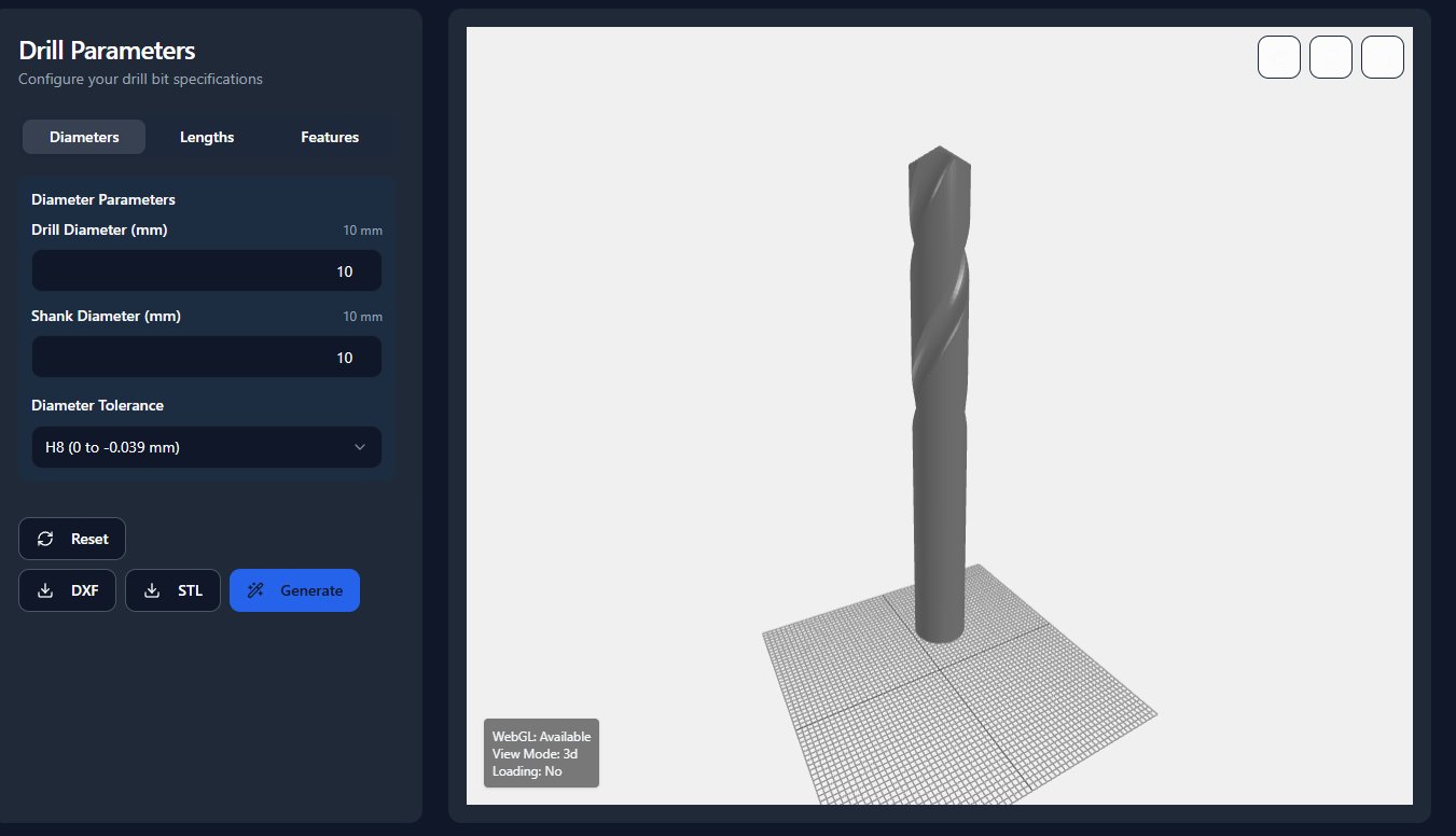
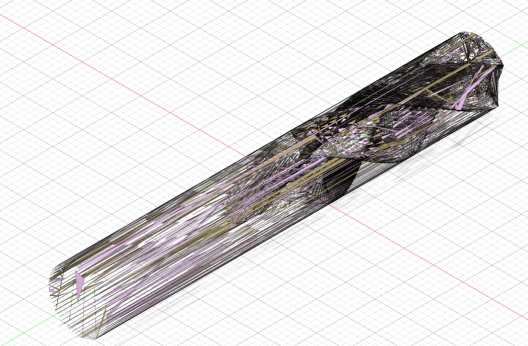
I have a project where i am implementing 3js for creating a drill which is based on parametric design, so far i have got everything to work as intended. I am using three-csg-ts for helix related operation. the main focus of the project was to get parametric drawings from web, i can make a model but when i export it (stl) for now, and when i try to draft it in fusion or any other software i only see meshes. I want the outside portion of the drill to be visible as these drawings should be appropriate for manufacturing of these components, i have attached some images of how the drawings currently look. I want a robust solution that can get rid of my problem once and for all.


I want everything to be done online and the export should be a .dxf file that can be drafted.
I hope someone can help me out with this.
Looking forward to learning and sharing more
Thankyou.

Yes, that’s what all of us are dreaming of :joy:. Unfortunately, this isn’t all that easy.

If you want to only visualize a spiral drill, I’m all for it, including maximum precision and all that! :+1:

BUT!

As I understand your post, you want to manufacture a drill using additive manufacturing, a.k.a. 3D-printing.

I’m not sure if you’ve ever tried to drill a hole with a positional accuracy of - say - 0.1 mm. That’s not easy in itself.

Then you probably want the drilled hole to be of cylindrical shape, which is also not easy to achieve.

Of course you’ll want to have the drilled hole to have the proper diameter, too.

Ultimately, you may want to drill a deep hole (depth > 5* ø), which comes close to the holy grail in precision drilling, combining all three/four requirements.

What I’m trying to convey:

A spiral drill is a precison tool, which has its properties and its cost. There are very cheap substitutes, but precision does have its cost, and there are no short-cuts or substitutes.

The very idea of creating a drill via additive manufacturing and receiving a result which even barely approaches the required level of precison is so outrageous that it makes me almost speechless.

Any support for this endeavour would be a waste of time, IMO:

I am sorry, maybe i was unclear with my description. I am not looking to 3d print drill (additive manufacture) with this. What i am looking for is a somewhat accurate drawing, i just want to make sure it will fit with my spindle correctly. Which i can verify with dxf, and i can also be using it for quotation purpose where it doesn’t matter if it is not accurate, what matters is i can do it fast.

Yes i want to visualize it, but i want it in autocad / other 2d software where i can mark dimensions atleast. currently i get a model and somewhat accurate of a dxf file too. I have attached it below, only issue is the unnecessary mesh lines, i want to have more control over the dxf file.

That is why i suggested that i required help with converting the model from mesh structure to solid model.
Drill_10mm_100mm.dxf (4.5 MB)
Please open it in any online dxf opener.

Something like that?

I think yeah i can make it work somehow. I think the idea of conditional edges is good. Thankyou for sharing how do i implement this?

Before you mentioned this, i had a look at it, the issue is it is based on bvh, I am currently using csg-ts. I used bvh earlier but due to some issues i had to switch over. To implement this should i switch back or what can i do to make use of it as it is?

You might be able to just build the bvh from your resulting geometry from whatever csg lib you’re using?
Do you have a link to the csg-ts you’re using?

I tried it out, seems like i will have to do a lot of things, as the export i got was a single line, compared to what i should be getting.

@gkjohnson Can i get some help, with the implementation steps of this repo GitHub - gkjohnson/three-edge-projection: Visible geometry edge projection and flattening based on three-mesh-bvh.

You’ll have to be more specific with what you’re having issues with. The repo includes documentation and examples on how to use each class. Each just takes a geometry.

I want to make use of the ProjectionGenerator. I tried it yesterday but could not get it to work, clearly am no Coding Mogul. I have a 3js model that am generating using three-csg-ts attached above. As far as i understand from the repo i need to use bvh mesh. So using the model and then building bvh for it and then projection generator which will give me flattened segments, which i can use to generate dxf and then finally export. So this is what i want.
I got it to work but all it exported was a straight line. Am not understanding what mistake i made. I will show you how my model looks like


Could you help me what the model should be like before going into project generator.
Project generator instructions are there
and then what will be the output so i can use and convert it to dxf.
Thankyou for your response

It doesn’t matter how the geometry is generated - the classes take any BufferGeometry. If you provide simple live example with something like jsfiddle I can take a look at what’s going wrong.

1 Like

I have made the default model as the drill that i generated. And then i used the same method. But as u can also see in the image that i see the meshes.

Are you using three r136 for a reason in this project? Have you tried updating to a later version of three?

In my project i was using 0.160.1 now i updated it to r175 as well. Where was i using 136? The github link i shared above it is using 134 as well

Maybe this file is irrelevant?

Yeah it was in the project repository because i was facing some issues with edge projection and clipper. I have updated it now. Maybe you can take a look at that and suggest something
cheers

I managed to get it working but i still see these lines.


Looking at the screenshot you can tell that there lines, which are not the part of the geometry like noise are coming. What can we do to remove that?