I entered the search terms “SRTM remove spikes” into Google and their “KI overview” returned the following:
To remove spikes from SRTM (Shuttle Radar Topography Mission) data, several techniques can be employed, including filtering, smoothing, and interpolation. These methods aim to eliminate erroneous data points (spikes) while preserving the overall terrain characteristics.
Common Techniques for Spike Removal:
- 1. Filtering:
-
Local Maximum/Minimum Filtering: Identify and remove points that exceed a certain threshold compared to their neighbors. This helps eliminate isolated high or low points that are likely spikes.
-
Median Filtering: Replace each data point with the median value of its neighbors. This effectively reduces the impact of outliers while preserving smoother features.
-
2. Smoothing:
-
Moving Average: Calculate the average elevation within a defined window and replace the center point with this average. This reduces sharp changes in elevation and helps to remove spikes.
-
Gaussian Smoothing: Apply a Gaussian filter to the data. This method uses a weighted average, giving more importance to nearby points, effectively smoothing out the data and reducing spikes.
-
3. Interpolation:
-
Kriging: A geostatistical method that predicts values at unknown locations based on the spatial correlation of known data points. This can be used to fill in gaps and smooth out irregularities.
-
Spline Interpolation: Fit a smooth curve through the data points and use this curve to estimate elevation values at missing or noisy locations.
-
4. Specialized Methods:
-
Low-Rank Sparse Method (LRGS): Developed for SRTM data, this method effectively removes mixed errors (including spikes) by associating group sparsity with the low-rank uniqueness of local transformations.
-
Regression Models: For vegetated areas, regression models can be used to correct SRTM elevation biases, potentially reducing the impact of spikes caused by vegetation.
Implementation in Software:
Offers tools like Point Filter with “keep maxima (with tolerance)” for spike removal.
Provides functions like “flood fill” and “Raster values” to handle spikes and null values.
Provides commands like “drop_below” and “drop_above” for outlier removal. However, these functions may not be suitable for all scenarios due to their reliance on absolute values.
Considerations:
The type of spikes and the overall terrain characteristics should be considered when choosing a method.
Select a software package and tools that offer the desired spike removal methods.
The desired level of accuracy should guide the choice of methods and parameters.
In some cases, spikes may be real terrain features (e.g., sharp peaks) and should not be removed.
- Remove noisy spikes from LiDAR data using SAGA GIS and SRTM …
23.07.2012 — * Select Module | Shapes | Points | Point Filter. The Points Filter dialog box appears. * In the Points field, choose t…
dominoc925
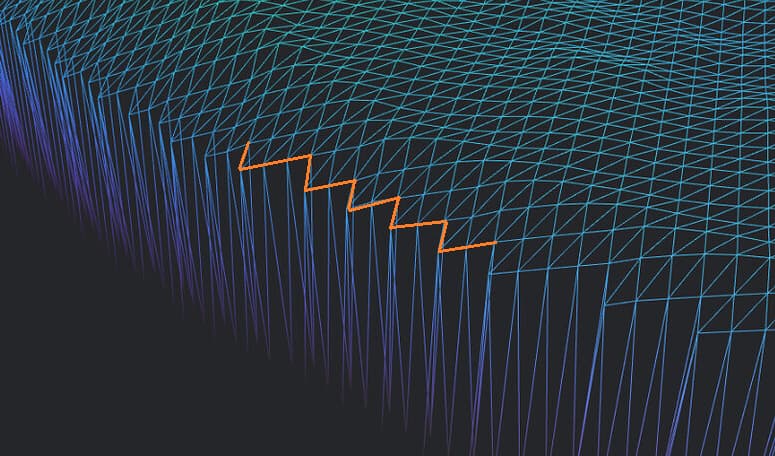
These points need to be removed from the point cloud prior to ground filtering, and can’t always be removed by drop_below or drop_
[image]
Google Groups
- Area S30E148 in Shuttle Radar Topography Mission 1 (SRTM 1) …
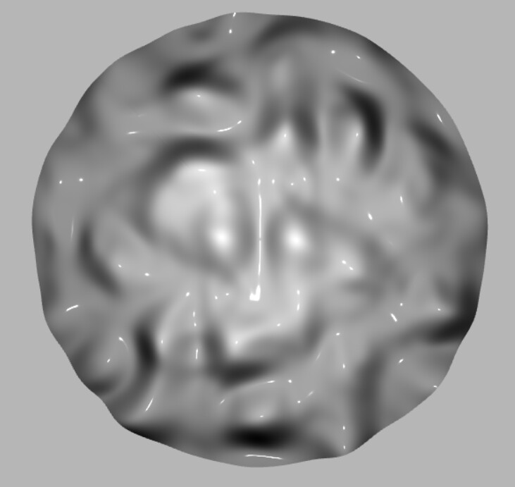
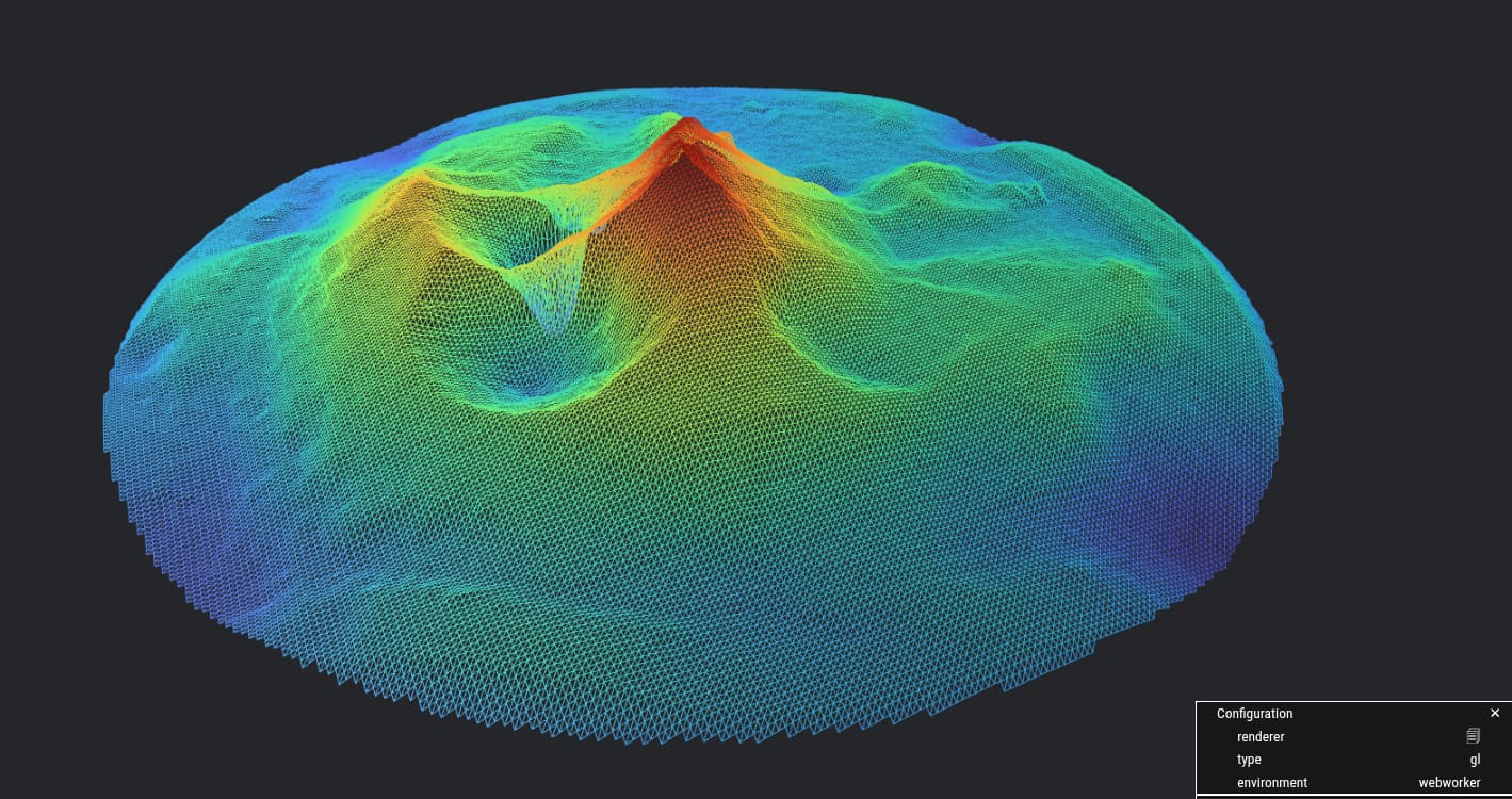
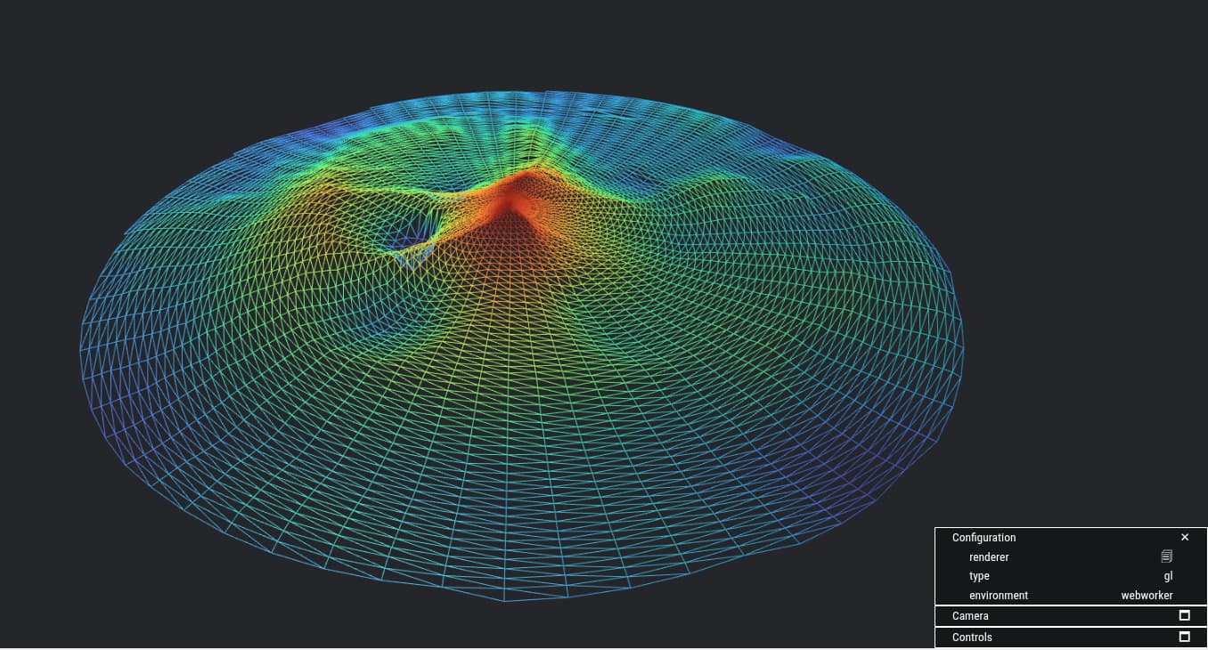
Area S30E148 in Shuttle Radar Topography Mission 1 (SRTM 1) containing spikes, speckles and multidirectional stripe errors (unit:
[image]
ResearchGate
AI responses may include mistakes. Learn more