Each Dot would be effectively attached to the camera at a fixed distance - so that the Dot would not change size (eliminating the need for a separate Ortho camera). For each Dot, I would create a “Rotator Mesh”, that is attached to the camera at 0,0,0. Then I would create a Dot (sprite) that is a fixed Z distance from the camera and attach it to the Rotator Mesh. That way, I could cause the Dot to move across the screen by rotating the Rotator Mesh.
I already have the steps to compute the Sun Offset - the difference between the sun direction and the camera direction (both lat and lon). So I merely need to rotate the Rotator Mesh (and the Dot) by some multiple of the Sun Offset. In the case of the “farthest” dot, that number would be less than 1. In the case of the “nearest” dot, that number would be greater than 1. It might be a constant number - or something more complicated.
Note - the Radius of the Dots could be small or large or the same. I could simply use different sizes to make the Dots look like they are different distances away. But I need to be able to turn them off when something blocks the Sun. The way to handle that might be to use a large distance so that whatever is blocking the Sun will also block the Dot. Of course, the Dot will have to be huge so that it will appear normal-sized at such a great distance.
At least that’s what I am thinking now. I will give it a try and see what happens.
Would lens flares not be attached to the “sun” as that’s where they come from? Testing the linked example above briefly earlier I noticed panning the camera is an issue, if flares would be connected to the position of the “sun” the camera is free to go wherever, flares would only occur when looking within the periphery of the sun…
The two distanced flares kind of “lookAt” the camera focal point whilst moving across the lense in a parralax fashion, this just feels like it should be mainly sun derived mechanics…
That’s what I originally tried to do. but I could not figure out how to recompute the coordinates of the Dots so that they would remain the same Z distance from the camera.
I have now got them connected to the camera - actually to a mesh that has the same rotation and position as the camera and which I have added to the scene to make everything visible. (Attaching things to the camera does not make them visible and if you add things to a scene to make them visible, they are no longer attached to the camera.) In any case, the Dots are now always directly in front of the camera and at the same distance. So I need to cause them to deflect laterally by some multiplier of the Sun Offset.
The problem is that I thought that I knew how to convert the camera Quaternion values to Euler values - but I don’t. (What I thought was converting from Quaternion to Euler was actually giving me back the Quaternion values - you learn something new every day!).
Until I figure that out, I can try making it work with one of my programs that has a Camera Rotator that uses Euler values.
Okay, new GitHub version working. Now you can scroll in and out and the Dots do not change size or position.
Since I have not (yet) figured out how to convert camera Quaternion values to Euler values, this one uses my own Camera Rotator that uses Euler values. So it is a good proof of concept.
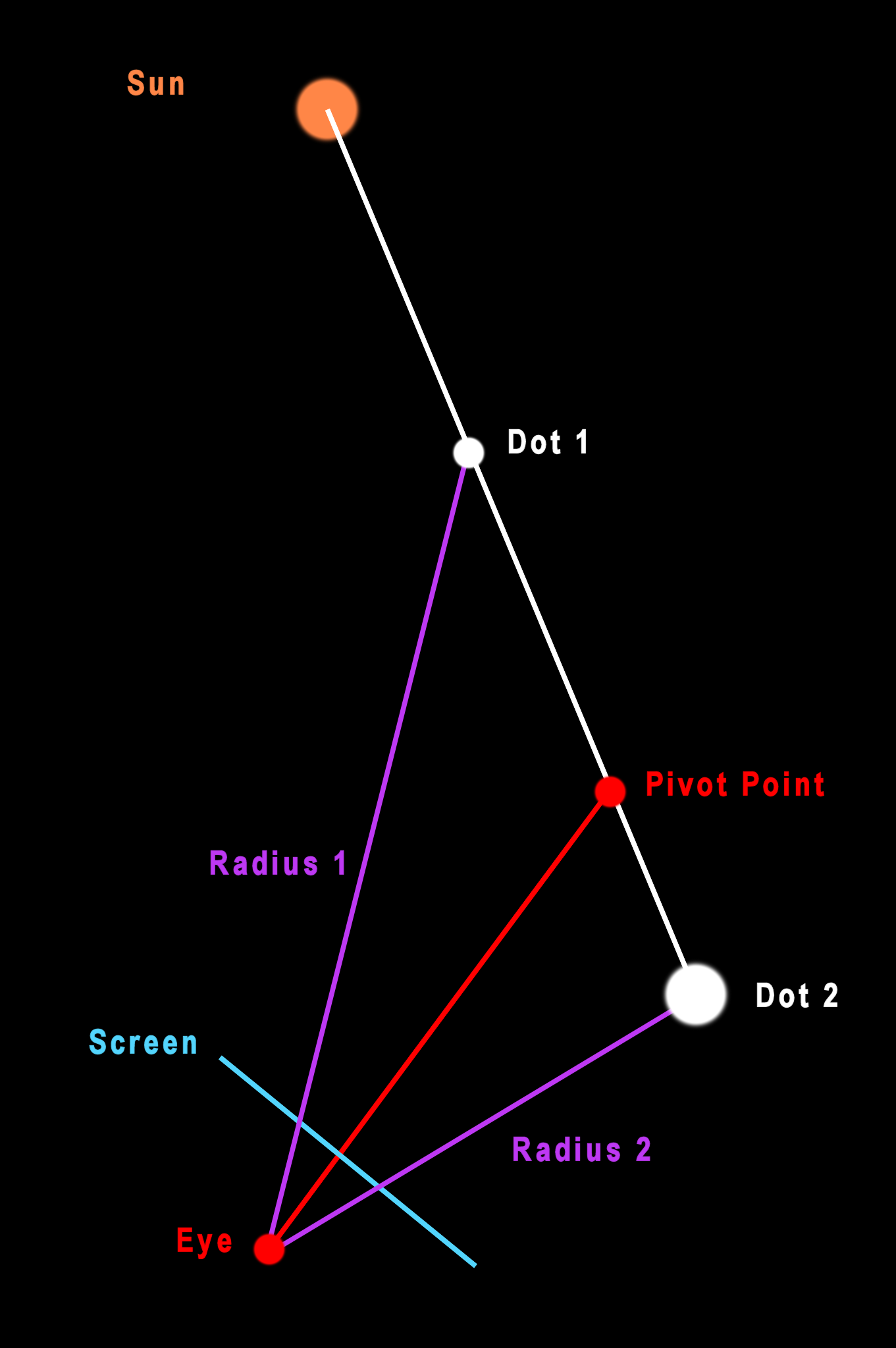
I have manually entered values for distance, scale and offset multiplier. But I am sure there is some kind of equation that will allow you to enter a single value that will compute all 3. Their distance could be identical - I just keep them apart to avoid conflict. That leaves only scale and offset multiplier. I believe the standard equation for computing size of an object is size/distance. I could use that to set the scale. The offset multiplier should be a similar amount - except that I also have to compute when the offset multiplier is positive or negative. I think that requires computation of a “pivot point” as shown below. This probably has something to do with the geometry of the camera lens - perhaps the focal point?.
BTW - I may have solved the problem with the SkyCube not loading. I simply had it enter a value of “1” to the LodFlg which is combined with the other value of “1” entered after initialization. Now the program will not render until the LodFlg value is 2.
Is there a way to adjust the opacity of the Dots? They are fine in a dark sky, but kind of get lost in a bright sky.
After many days (and nights), I have created a little demo program that includes functions that create what I call a SunFlare - a LensFlare created by the Sun. These functions work with both WebGL and WebGPU and do not change size as you scroll in and out. They also work with OrbitControls - but you need to set a flag. (You can copy the demo program and run it locally.)
Or you can see it online. I am trying to convert it to a module, but am having some difficulty making the module work with OrbitControls.
For some reason, I was able to attach the sprite rotators directly to the camera when using my camera rotator. But for OrbitControls, I had to link them to a mesh which has the same rotation and position as the camera.
To improve visibility, the program loads a custom transparent hexagonal texture- so you can adjust opacity, color, etc. But you should be able to pick whatever material you want.
Why an OrthoCamera? Wouldn’t adding second camera slow things down? And how would that work together with the main camera? (This is an area I have never explored, so I am curious.).
Since I am trying to maintain frame rate and don’t want overdo things , my efforts were aimed at creating a minimal version of this effect, with only 2 or 3 hexagonal reflections:
EDIT: Note that I am already using an OrthoCamera in the sense that the sprites are all the same distance from the camera (10k meters). When the sprites are deflected, they are orbiting the camera and should remain the same size because their distance from the camera is unchanged. But I expect that the PerspectiveCamera does not use true distance, but uses z-distance from the camera. In theory, this could cause a change in their sizes, but at that distance, the apparent change is minimal. So, I might already be achieving the benefits of what you expect an OrthoCamera would provide.
I am using orthocamera for flat ui icons like bullet damage, health, distance to target and want to try place lens here too, maybe it wiil be easy then perspective camera.
Yes, I definitely see the benefits of using the orthocamera for all kinds of things.
My approach computes the difference in direction between Camera direction (Lat/Lon) and Sun direction (Lat/Lon) in degrees (Lat/Lon). If you want to use that approach on your orthocamera, I think the only change you would would have to make is to convert the degrees to an equivalent lateral XY displacement. For example, a single degree of displacement might equal 10 pixels.
For better or worse, I have created a post un the Resources category which describes my SunFlare module. To avoid confusion, I have deleted some of the interim programs linked above. Here is a link to a program demonstrating the module. This program uses the OrbitControls module.
FYI: A Lensflare port for WebGPURenderer will be available with r169 as LensflareMesh with a respective example (webgpu_lensflares).
The flare colors will look a bit different though since the new implementation handles color spaces more correctly than before. So make sure you mark you flare textures as sRGB e.g.:
Besides, you might want to make the flare color values a bit brighter. Since the blending is now performed in the correct color space as well, you might have to increase the intensity of flare textures to restore the previous look.
That’s great news! My interim solution still needed some work.
I assume that the textures will be the more common version where png textures have a transparent (rather than a black) background and that - hopefully - we will be able to do some node tricks like creating rainbow-colored materials?
Um, I’m not sure what you mean with rainbow-colored materials. It’s an almost 1:1 port so what you can do with the previous version should also be possible with the new module.
Perhaps the term I should have used is iridescence - similar to the lighting in the loader/gltf example with the lamp. I accidentally created an iridescent texture in one of my many experiments and that is what got me to thinking about it. Do a google image search for iridescent lens flare (or rainbow lens flare) and you will see all kinds of examples.
I wouldn’t want to overdo the effect in my programs which have a more muted color palette since that would be distracting. But it could look great in programs showing scenes in outer space.
I found the r169 WebGPU Lensflare example, but the code appears to be missing.
If anyone needs to see it, I have loaded the file and saved the source code to my GitHub repository…
There appears to be some kind of interference between Bloom and LensFlare.
I added the LensFlare module to my program and then tried to add Bloom to some bullets (represented as lines). It worked great until I turned toward the Sun - then the program froze. I would have assumed that the problem was with Bloom, except that the error messages mentioned LensFlare.
Here is a stripped-down program that demonstrates the problem This loads a SkyCube with LensFlare and a couple of lines, the left one has bloom applied. The lines are a bit hard to see, but that isn’t critical. Instead, note that, when you turn left to look at the sun, the program freezes. If you are using Chrome, the console will list a long error message that references LensFlare.
The source code is here. Is this a programming problem on my side or is this just “growing pains” for LensFlare?