Hi there,
i’ve got this mesh in blender, that i want to export as a threejs path / shape:
Is there a convenient way to do it? I imported it as glb and extracted the points and tried to set a shape from those points that did not work out well.
My main goal is to import meshes from blender and extrude them in threejs programmatically, therefore i need to make a shape out of it right?
here is the blend file:
untitled.blend (859.2 KB)
Do you have a reference to what the outcome of this was, an image, or console log? That’s sounds like the way it would be done…
Thats what i get:
My code:
  const vertexArray = nodes.Curve010.geometry.attributes.position.array;
  const pointsArray = [];

  for (let i = 0; i < vertexArray.length; i += 3) {
    const x = vertexArray[i];
    const y = vertexArray[i + 1];

    pointsArray.push(new THREE.Vector2(x, y));
  }

  const shape = new THREE.Shape(pointsArray);
looks like the order messes up in which the points are connected.
Here is a codesandbox of the issue:
https://codesandbox.io/p/sandbox/3vs7g3
For some reason the result here looks different. To get this result i needed to fill the vertices in blender with a face. Without it i could not export it as a glb file.
Can you export it as svg and use threejs svgloader?
Yes there’s something very odd with the order of vertices in the original blend file, how did you generate the shape? Try the svg route @manthrax has suggested above and report back…
After two hours of trying i could not get it to work, here is the svg i exported from blender (too big i know):

here is the code where i am trying to import:
import { Edges, useGLTF } from '@react-three/drei';
import * as THREE from 'three';
import { SVGLoader } from 'three/addons/loaders/SVGLoader.js';
import { useLoader } from '@react-three/fiber';


export const Dichtung2D = () => {
  const svgData = useLoader(SVGLoader, './12340001.svg');

  // Extract shapes from SVG paths
  const shapes = svgData.paths.flatMap((path) => SVGLoader.createShapes(path));

  return (
    <>
      <mesh>
        <shapeGeometry args={[shapes[0]]} />
        <meshBasicMaterial color={'red'} side={THREE.DoubleSide} />
        <Edges color={'#000'} lineWidth={3} />
      </mesh>
    </>
  );
};
never mind the above approach works. But how can i make sure, that the scaling is right?
There is an option in the Blender glTF exporter to include “Loose Edges” in exports, I think that’s all you need to get the original lines in the GLB. It will come in from GLTFLoader as a THREE.LineSegments instance.
Wooow, thanks a lot!!
I read about the ‘Loose Edges’ export setting and tried it at first. I was not aware i also needed to enable ‘Loose Points’ so the exported glb was empty…
That is exactly what i was searching for thank you!
Here is the full code:
import { Line, useGLTF } from '@react-three/drei';
import * as THREE from 'three';
import { extrudeSettings, matExtrude, matShape } from './utils/utils';

export const Dichtung2D = () => {
  const { nodes } = useGLTF('shape.glb');

  const vertexArray = nodes.Shape.geometry.attributes.position.array;
  const pointsArray = [];

  for (let i = 0; i < vertexArray.length; i += 3) {
    const x = vertexArray[i];
    const y = vertexArray[i + 1];
    pointsArray.push(new THREE.Vector2(x, y));
  }

  const shape = new THREE.Shape(pointsArray);

  return (
    <group>
      <mesh material={matExtrude}>
        <extrudeGeometry args={[shape, extrudeSettings]} />
      </mesh>
    </group>
  );
};
@donmccurdy one more question about this, i hope you have experience with that. What defines the order of the points that get exported?
For my previous shape everything went fine, now i made another and it is a bit off:
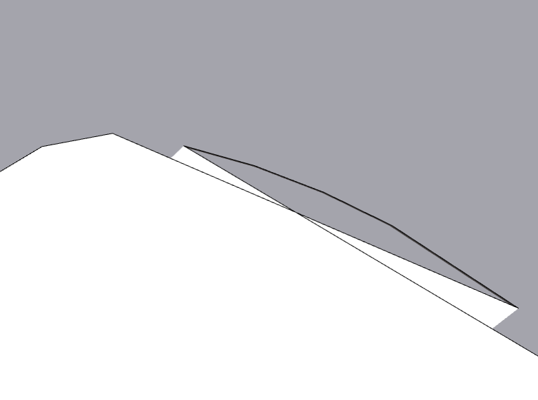
I used your viewer and turned on wireframe to check where the edges go:
So basically i noticed that the vertices are connected not in the right order. Viewing into the glb data i imported into three i could confirm exactly that. The point before the last point is not correct, thats why this wrong line exists. I could manually change the position of the point in the order to solve it but i wanted to know if you ever had such cases while exporting from blender.
Here is the .blend file:
testShapes.blend (911.7 KB)
I looked into this:
the testShapes.blend file you attached seems completely sane. Selecting the “critical” vertices in Edit mode highlights (the fading orange line) both segments leading up to, and away from the selected vertex. For all vertices fully including your reported error region. No hidden or triple connections whatsoever.
Testwise filling the shape in Blender did not reveal any irregularities either:
Exporting the filled shape as glb and viewing in glTF Viewer (wireframe mode) looks like this (nothing of note for me):
I’m inclined to rate this bug report “not reproducible”.
P.S.: I do note however, that the “islands” were not included in your testShape.blend. . So there’s a slight chance they might have anything to do with it.
P.P.S.: I’m using Blender 4.2.3 LTS
Hey @vielzutun.ch,
Thanks for the report. I did already check those things in blender aswell because not applying scale/rotation or double vertices often lead to such issues.
The issue does not appear if you make a mesh out of it in blender by filling the shape.
What i do is exporting the vertices and edges only as donmccurdy showed before.
What i am showing in my screenshots is the result of the glb file created by this export and using it in my code / viewing it in donmccurdys viewer.
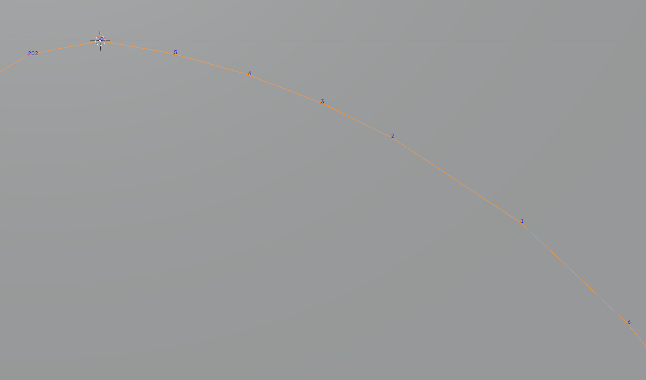
Here is whats the issue i tried to make it clear with a screenshot from blender:
- (1.) is the first point in the geometry.
- From there it goes a few vertices in the “wrong” direction
- Then it turns in the “correct” direction and goes perfectly around the shape
- and then it comes back around the shape to the origin vertice
- Thats why the shape looks weird at this part
I hope i could make it more clear whats the issue here:)
P.S. I already tried the latest blender LTS Support 4.2
The ‘wireframe’ mode in my viewer is equivalent to setting .wireframe = true on a material. TBH I’m not sure what happens for a THREE.LineBasicMaterial (which should be what you get here) because the .wireframe property isn’t documented for it, I didn’t think it existed, that property is meant to apply a wireframe mode to a THREE.Mesh. Arguably a bug in my viewer and/or three.js. I believe the data is correct, like what you see before switching to wireframe mode.
Well although it is not intended to do it it showed me the issue before importing it into threejs.
I asked ChatGPT what the problem could be and it answered this:
How Blender Orders Vertices
- Creation Order: Initially, vertices are ordered based on the sequence in which they were created. The first vertex added to the mesh gets index
0, the second gets index 1, and so on.
- Editing Operations: Any mesh editing operations (e.g., adding, deleting, or merging vertices) can disrupt this order. Blender may reassign indices based on internal optimization or topology changes.
- Export Process: During export, Blender may reorder vertices to optimize the file for rendering or based on the requirements of the export format (e.g., GLTF, OBJ). Loose edges and points are particularly prone to reordering because they lack face connectivity.
I recreated the shape and focused on keeping the right order and not merge any of the vertices.
Now it looks a bit better but the issue is at another spot of the shape much less noticable.
I can live with this small error for now. If i got time i’ll dive into it further. Here is the result:
Thanks for your elaboration.
What I do see in your .blend file is, that you are using really tiny distances.
M(erging) selected vertices by a miniscule distance: (0.00003 m - four zeroes post decimal point!) already welds the two vertices marked red. You may well be the victim of limited precision somewhere.
Good point! But there are no missing vertices in threejs so blender does not merge some of them while exporting.
I think i found the problem. Here is a screenshot from Blender and threejs:
Blender:
Threejs:
You can clearly see the id of the vertices are the issue here.
I fixed it by reordering the vertex ids in Blender.