This is an incredibly hard problem, and approaching it in 2d only is entering a World of Pain.
Some introductory reading:
then.. specifically addressing how CLO3D does it:
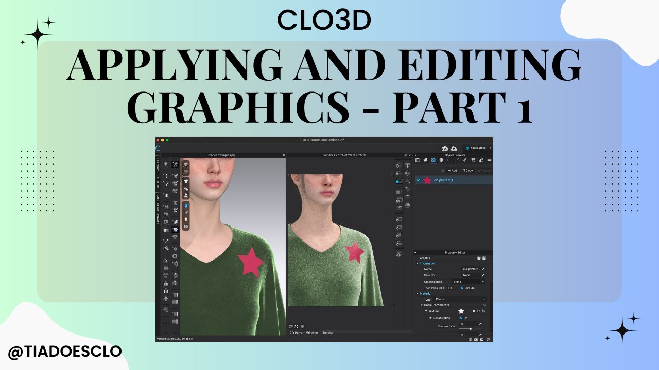
Yes, CLO3D (and its sister software, Marvelous Designer) is the gold standard for fashion design and digital apparel. Its feature for stretching graphics seamlessly across panel seams is called “Graphic Over Seamline.” CLO3D can achieve this because its core architecture is fundamentally different from a standard 3D web application. It does not treat the garment as a static 3D mesh; it operates simultaneously in 2D pattern space and 3D simulation space.
The software relies on three main technical approaches to cleanly project graphics across broken UV islands:
1. 3D Spatial Intersection & Co-planar Mapping
When a designer drags a decal across a seam in CLO3D’s 3D viewport, the software completely ignores the 2D UV layout at first.
Raycasting the Projector: The decal is treated as a 3D planar projection volume (a frustum or bounding box) shooting a vector down onto the 3D garment.
Finding the Intersecting Panels: The software calculates which 3D polygons fall inside that projection volume. If a seam divides a jacket down the center, polygons from both the Left Front Panel and Right Front Panel are flagged as intersecting.
Calculating Local 3D Coordinates: For every vertex or face inside the zone, CLO3D calculates exactly where it sits relative to the 3D decal’s local coordinate matrix.
2. Utilizing the Sewing/Topology Graph
This is the hidden advantage that CLO3D has over raw 3D engines like Three.js. CLO3D knows exactly how the garment is stitched together because it manages a Sewing Relationship Graph.
If a user drags a graphic over a seam in the flat 2D pattern window instead of the 3D window, CLO3D uses this graph to handle the math:
It checks the Sewing Line data structure. It knows that Edge E_1 of Panel A is sewn to Edge E_2 of Panel B.
It calculates the exact geometric transformation offset (the positional gap, the angle of the seam, and the grainline direction) between those two pattern pieces.
It instantiates a hidden “Child Bounding Box” on the connected panel. If you move, scale, or rotate the primary graphic on Panel A, the software uses the sewing transformation matrix to automatically translate, shear, and mirror those exact transformations onto the cloned graphic bounding box on Panel B.
3. Headless Ray-Traced Texture Baking
Ultimately, game engines and web viewports cannot read CLO3D’s dynamic, live 3D projection data structure directly. To solve this, CLO3D features a built-in UV Editor & Texture Baker.
When the user exports the garment, CLO3D executes a Texture Space Rasterization pass:
It loops through every pixel (texel) of the output 2D UV texture map.
For each texel, it maps the (u,v) coordinate back to its precise (x,y,z) coordinate on the 3D simulated mesh.
It checks if that 3D coordinate falls inside the decal projector’s influence.
If it does, it samples the pixel color from the decal texture and writes it directly onto that spot in the flat 2D diffuse map.
To avoid ugly seams due to texture filtering in engines like WebGL, it applies a “Fill Texture Seams” (Dilation/Padding) algorithm, which pushes and bleeds the edge pixels outward past the UV boundary lines by a few pixels.
You use a 3d decal volume to show the placement in 3d…
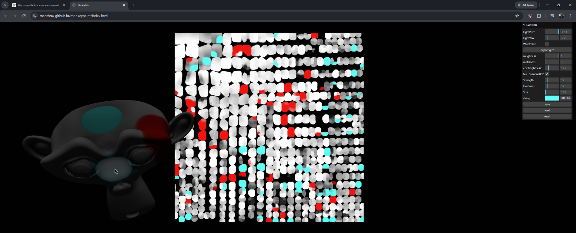
You then render to the UV map, using the UVs as the vertex coordinates, and the vertex coordinates as the UVs (swapping UV and Position)
For each fragment in the UV map, you look up the corresponding point in 3d space.. compute the intersection of this point with your decal volume box… and pull the texture color from that intersection point.
This gets you the very basic first step. Then you have issues with textures bleeding across the UV island boundaries.
It turns out that simply filling the shapes on the UV map is not enough.. the color has to bleed out across the boundaries of the UV islands to prevent filtering artifacts at the seams…
This can be accomplished with a texture dilation shader.. which re-renders the UV map, and for texels outside of the UV map, pulling the nearest in-map texels.. to bleed the texture out into a 16 texel skirt around each island.
This is all really tricky stuff.. and requires writing multiple shader pipelines.. the UV baking shader… a UV mask generator (generate the inside/outside mask for the dilation shader)
Then the dilation shader, which runs in multiple passes, bleeding the island perimeters out 1 pixel at a time.
This is all hard stuff.
I implemented something similar for a client (AI texture baking) and it took ~ a year to get it usable.
I think you’re 100% better off creating an extra UV map that actually follows your logic; eg join left and right half of the front into one. Or at least have them line up correctly without mirror or scale transforms.
From three, you can access different UV maps on the fly and per map. So have orm+normal use UVmap1, and have your albedo use UVmap2.
[edit] I’ve built these kind of systems before and have most of it at the ready. DM if you want to explore
that makes it even less convenient. You have zero control on what is being uploaded. Your example has clean islands, but this could be totally fragmented in any other model, depending on the author and authoring tool.
You could follow manthrax’ explanation. But you’re basically rebuilding Clo from that point..
- Use two UV channels: UV0 (standard multi-island layout) and UV1 (single, continuous island specifically for decals)
- Decals use UV1, which has no seams, so they appear as EXTEND (continuous) rather than DUPLICATE
- This works perfectly with baked texture pipelines and adds no geometry (Roblox-friendly)
Implementation options: users prepare UV1 before uploading, or we auto-generate it at upload time.
Questions for feedback:
1. Is this feasible for our use case?
2. Should we require user-prepared UV1 or build auto-generation? What do you think about auto-generating this UV with one island based on the 3D model?
3. Could UV1 serve other purposes (lightmaps, AO)?
Yep that would be my approach. If its feasibly for you I don’t know, Even autogenerating UVs can yield unexpected results, as any 3D artist will tell you. UVunwrapping is a skill in itself.
I’m using semi auto UV generations for the gradients here, though still per panel. (decals are position locked atm but could use the same logic).
And even then it’s still heavily dependent on the model’s initial UV island transforms.
I’m pretty confused with this entire thread. My understanding is that the bird graphic need to be projected onto the shirt model. The image is thus shown in the wrong space. It simply won’t be rectangle in uv space, it can be projected there sure, but it doesn’t start there.
Guys this is the result of this research maybe helpfull and let me know your idea
Overview of the Proposed Solution
A practical approach for handling decal continuity across surface boundaries in 3D assets is to separate concerns between texture layout and decal projection using a dual-UV strategy.
Core Concept
A two-channel UV system can be used:
The primary UV layout is responsible for standard texture baking and remains the main mapping for the final output texture.
A secondary UV layout is reserved exclusively for effects that require continuity across surface discontinuities, such as decals spanning multiple mesh islands.
Processing Strategy
During the texture composition stage, decal rendering is split into two paths:
Standard decals are directly applied using the primary UV mapping onto the final texture target.
Cross-surface decals are first evaluated in a separate intermediate space using the secondary UV layout to ensure continuity.
Both results are then merged by iterating over mesh triangles and transferring information from the secondary UV space back into the primary UV texture domain using barycentric interpolation at the pixel level, while respecting layering and depth priority.
This hybrid mapping approach eliminates the need for explicit 3D projection logic while maintaining consistency in the final baked output.
Generating the Secondary UV Layout
Since assets often come with only a single UV set, a second UV channel can be introduced through different strategies:
Automatic generation approach
A geometry unwrapping process can compute an optimized, non-overlapping UV layout.
This produces a continuous mapping suitable for effects that require cross-island consistency.
It is generally the most robust option for general use cases.
External DCC tool workflow
A modeling tool pipeline can be used to generate an additional UV set before export.
This provides full artistic control but shifts responsibility to the content creation stage.
Manual workflow guidance
Advanced users can define a second UV set manually in standard 3D modeling tools.
This is flexible but not scalable for non-technical users.
Development fallback
The existing UV set can be duplicated as a temporary second channel.
This is useful for validating pipeline logic but does not resolve discontinuities in practice.
Alternative Approach Using Geometry-Based Projection
An alternative method avoids UV dependency entirely by operating directly on mesh geometry.
In this approach, a localized 3D region is used to detect affected triangles around a decal placement. Spatial acceleration structures are used to query intersecting geometry efficiently. These triangles are then projected into a local decal space and rasterized into a 2D buffer, which is finally written back into the texture using the primary UV mapping.
Trade-offs of the Geometry-Based Method
This approach introduces additional complexity in multiple areas:
Depth ordering must be explicitly managed for overlapping geometry.
Edge artifacts may appear at UV boundaries and require post-processing to mitigate.
Performance optimization is necessary for high-density meshes due to real-time rasterization cost.
Additional handling is required for filtering artifacts and boundary precision issues.
Conclusion
A dual-UV strategy provides a simpler and more maintainable pipeline with predictable performance characteristics, while geometry-based projection offers greater generality at the cost of increased implementation complexity and system overhead.
This too, just ask Claude to do it, it’s super smart nowadays. I’m actually a bit surprised there is a need to ask in a forum. You can also just paste this entire thread in it.